Making my own data logger module for Solis inverters with ESPHome
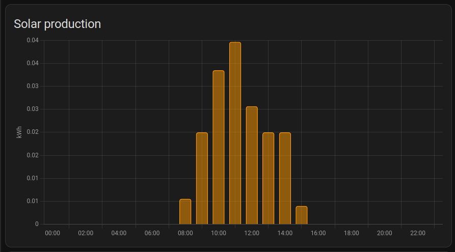
Our house is a new build and came with solar panels already fitted. I like having data about my stuff, and have previously attempted to monitor the solar power generation using Home Assistant Glow, which uses a photo-diode to count the LED pulses at the generation meter and push that data into Home Assistant. It is however quite inaccurate for my use case, as at dawn there's a period during which the light level is just enough to power the inverter for a second or two and then it cuts off again, and with each cycle the LED at the meter blinks once without actually having generated 1Wh, resulting in a disproportionately large and incorrect estimate for the first hour of sunlight.
This post is my little adventure (and a guide of sorts) in building a thing™ that can get this data straight from the inverter to Home Assistant, all ewithout going through anyone else's computer.
The obvious idea I somehow didn't consider
"Man, it would be so nice if I could get this data straight from the inverter, but it seems to be a very crude device, I don't think it will have support for it." - Past me, an idiot.
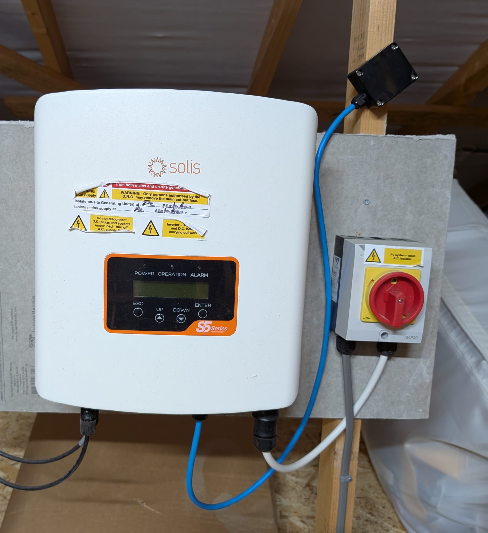
After several years living here, only now it has occurred to me to search if this was an option and, surprise surprise, it is! Our inverter is a Solis (Ginlong) S5 something-something, and it comes with a green data port at the bottom that's meant to be used with their first-party data loggers. Great, just buy one of these and problem solved, right?
Unfortunately, these devices send your power statistics (and who knows what other information) to their "Solis Cloud", an online service that requires registration bUt Is FrEe-Of-ChArGe (what could possibly go wrong?!). The cherry on top: accessing the data needs to be done via their web portal or app. 🤮
We can rebuild it, we have the technology
Googling a bit more revealed that this green port actually speaks a standard protocol (MODBUS over RS-485), and thanks to the efforts of several amazing people, all of the components required, the MODBUS addresses, and the general build process are relatively well-documented.
I would like to thank the maintainers of the following repositories, which were my main references during this process:
"But, if these projects already exist, why not simply use one of them?" The thing is, I like ESPHome, and I was pretty sure I could replicate the same results with a lot less code and in a more "noob-friendly" way, so here we are.
The Bill of Materials
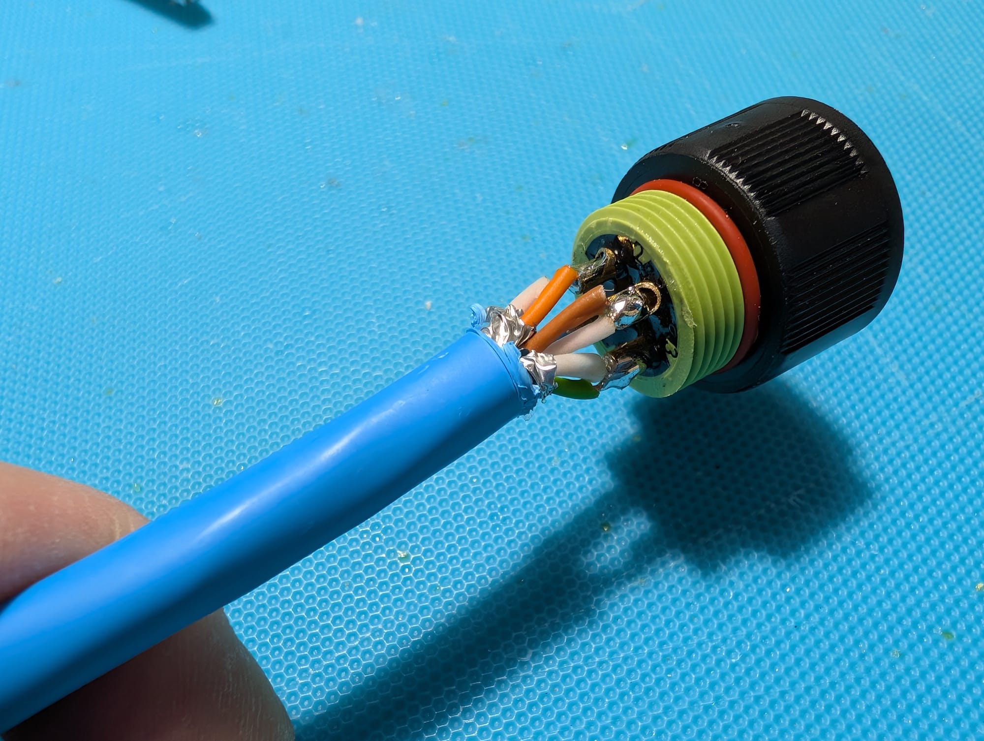
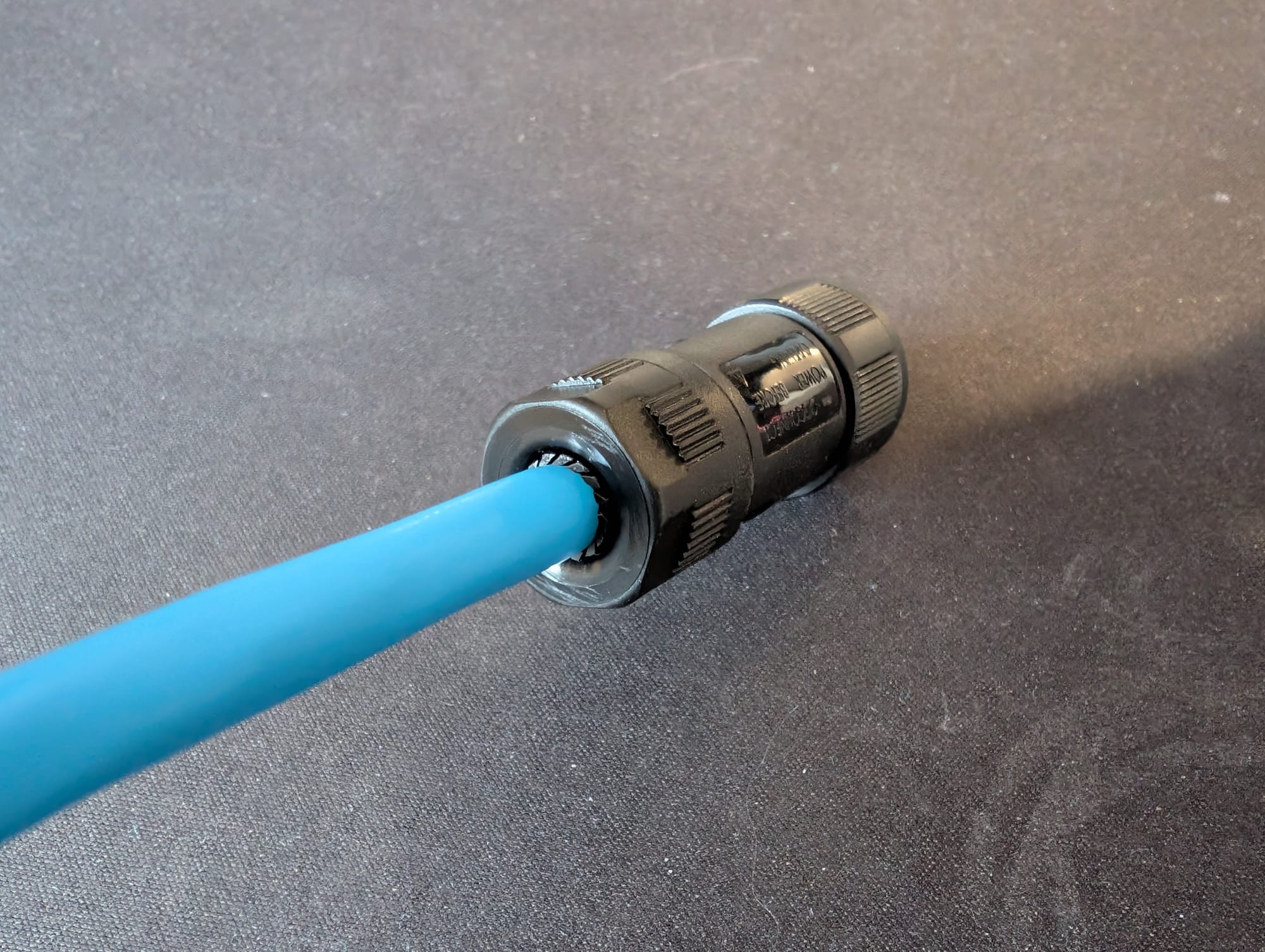
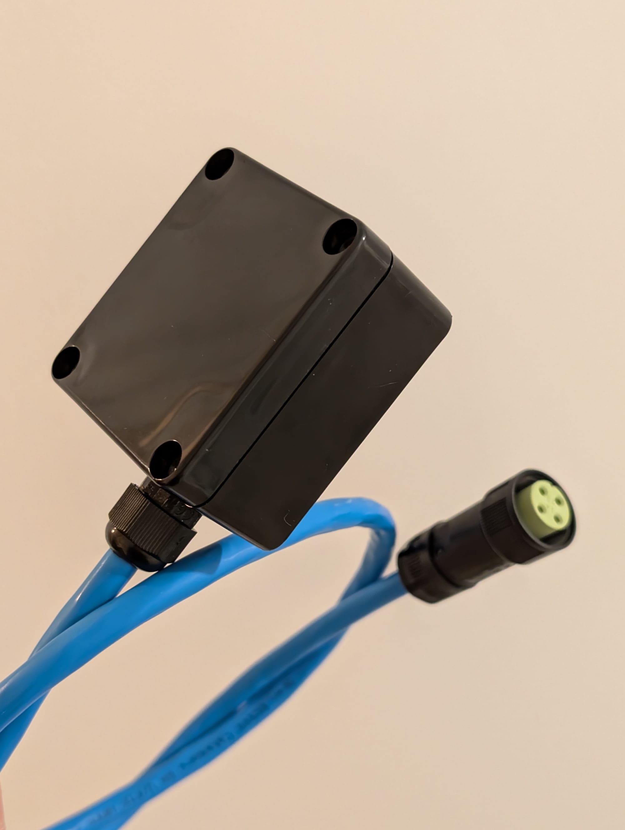
- Exceedconn EC04681-2023-BF connector: (https://www.ebay.co.uk/itm/204361478937). This is the most expensive component of this build (yay proprietary crap!)
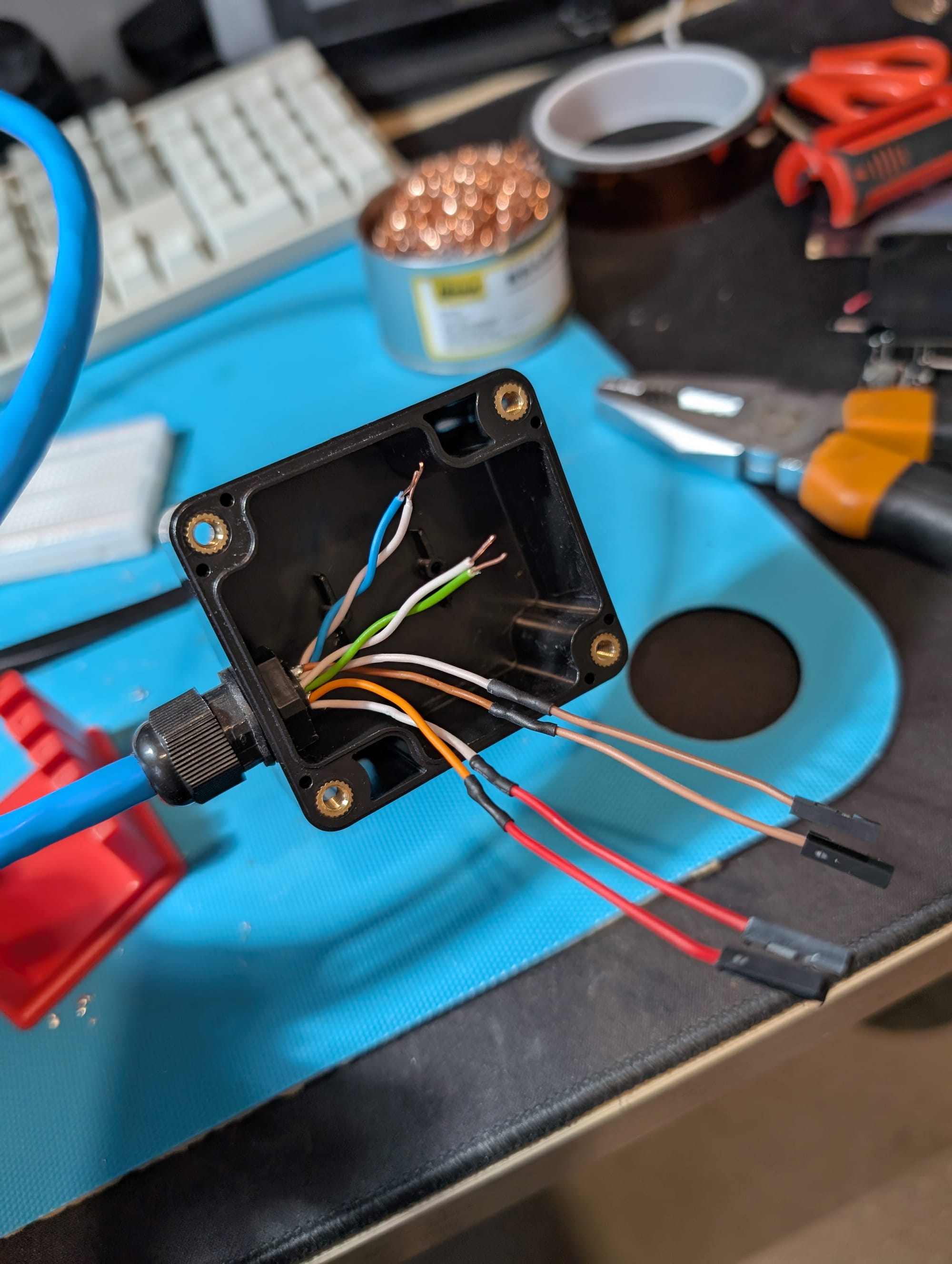
- Approx. 1m of cable. I used CAT6 and treated each pair as a single wire, but anything with 4 wires should work.
- A project box that can fit your components (or leave everything hanging exposed, you do you).
- PG7 cable gland (very optional, but gives it a professional look).
- RS-485 to UART converter: https://www.aliexpress.com/item/1005006825563125.html. Mine is based on the MAX13487 chip.
- 5V to 3.3V buck converter: https://www.aliexpress.com/item/1005007510639297.html. While this can technically be skipped and the 5V from the inverter connected directly to the ESP32's
5Vpin, this would use the integrated linear regulator to produce 3.3V, which generates heat. My inverter is in the attic, where it gets quite hot during summer, so the less heat the better. - Wifi-enabled board supported by ESPHome: I used an ESP32-C3 Super Mini. I love this tiny board https://www.aliexpress.com/item/1005006960134338.html.
- A bunch of wires. I used jumper wires to make sure I could disconnect any part in case it broke or I made a mistake, but hard-wiring is fine too and could have made mine look a lot cleaner.
- Patience.
Wiring It Up
The connector from the inverter has 4 pins (clearly labelled on both sides):
/-----\
| 1 4 |
| 2 3 |
\--^--/
Pinout representation - credit to https://github.com/hvoerman/solis2mqtt
- Pin 1: 5V
- Pin 2: Ground
- Pin 3: RS-485 A/+
- Pin 4: RS-485 B/-
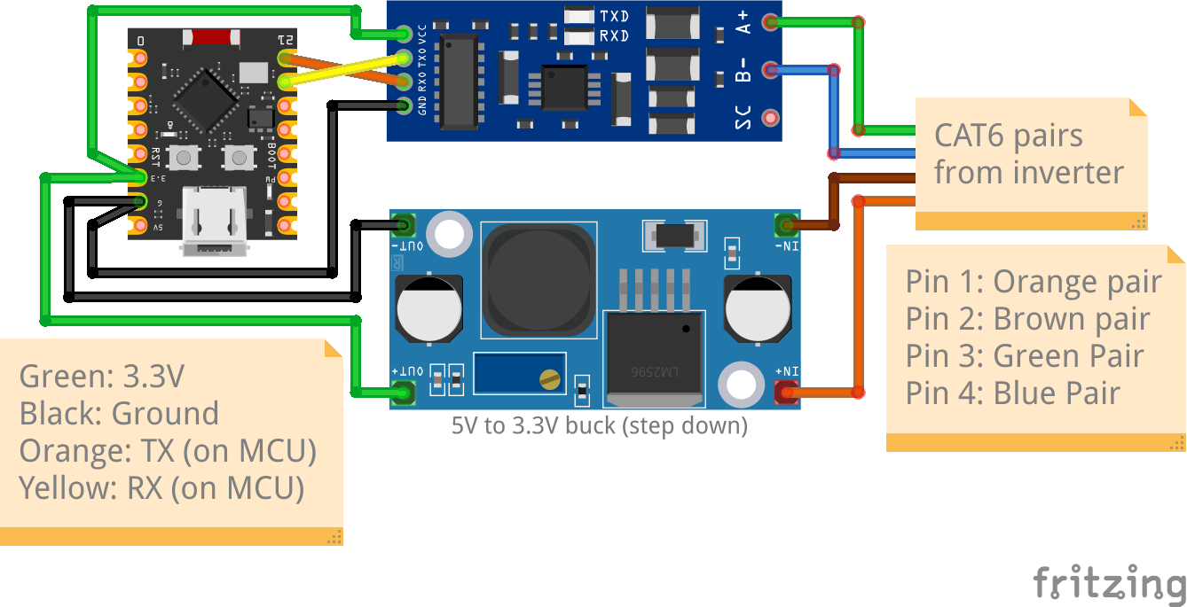
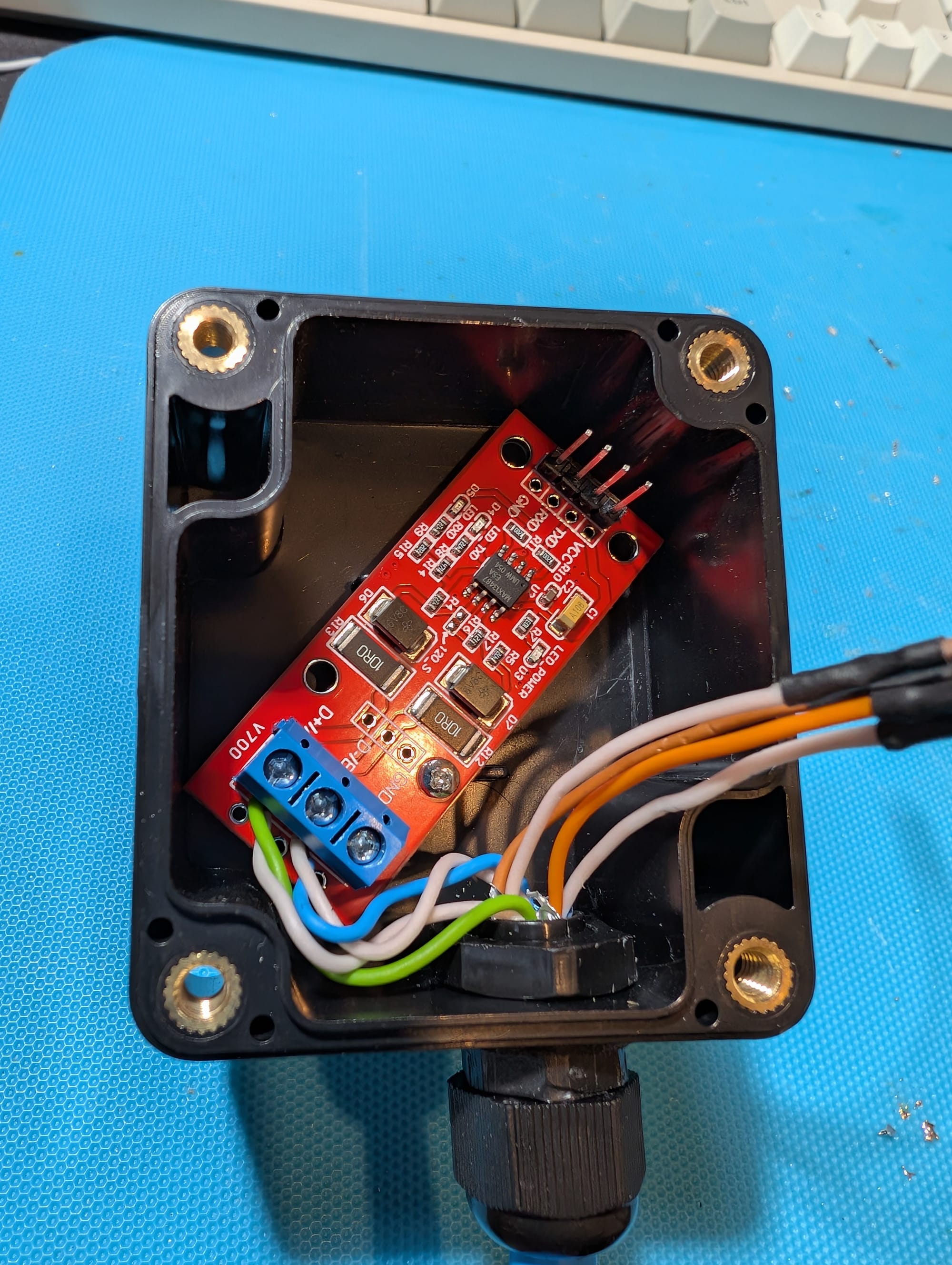
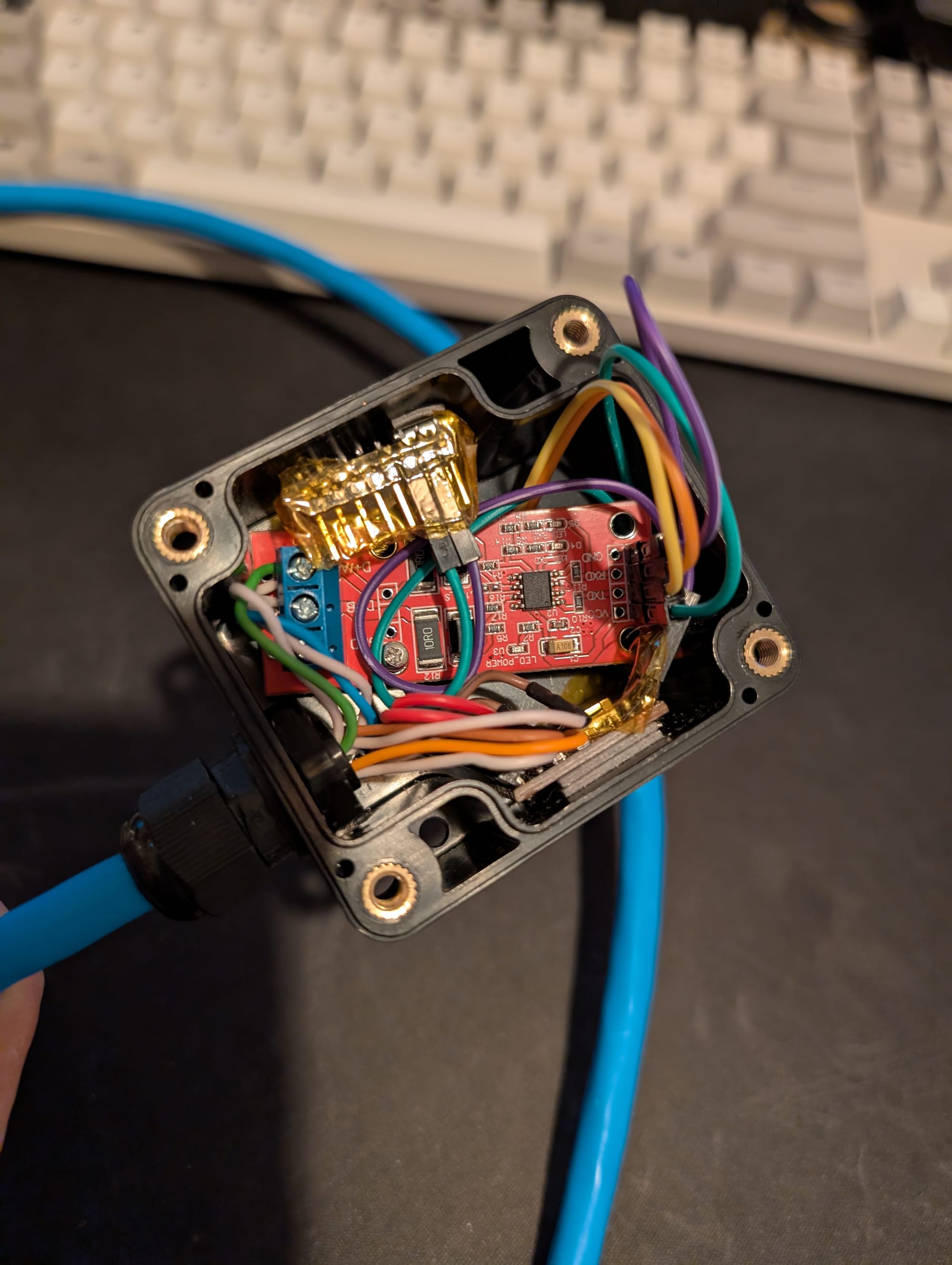
The idea is to connect the power coming from the inverter to the DC-DC step-down converter, and then feed 3.3V from it to the ESP32 and to the UART to RS-485 bridge. The A and B wires connect directly to their respective terminals on the bridge. The TX pin on the ESP32 connects to the RX pin on the bridge and vice-versa.
Alternatively, if heat is not a concern, you could ditch the step-down converter and connect the 5V from the inverter directly into the 5V pin of the ESP32, and feed the bridge from the 3.3V pin, but that is not the way I went.
Below you can see roughly what mine looks like:
The Code (wo-oh-oh)
Again, thanks to the two repositories I mentioned above and to ESPHome's great documentation and examples, getting it to work was easier than I anticipated.
I have put the code in this repository.
Create a new device in ESPHome for the type of board you are using and add the contents of solis-data-logger.yaml to it, then compile and install. That's it, done!
If all goes well, once connected to the inverter and receiving power, you should see the usual notification in Home Assistant to add the device. You can then add the sensor Generation Today (calculated) to your Energy Dashboard.
Photos
Future Improvements
I don't know if it's worth the hassle, but one thing I'm considering for a future update is to include a small battery to keep the ESP32 alive when the inverter powers down at night. We'll see...